Translate

Sunday, November 6, 2016

Pre Election Special - What’s Really Happening With The US Economy


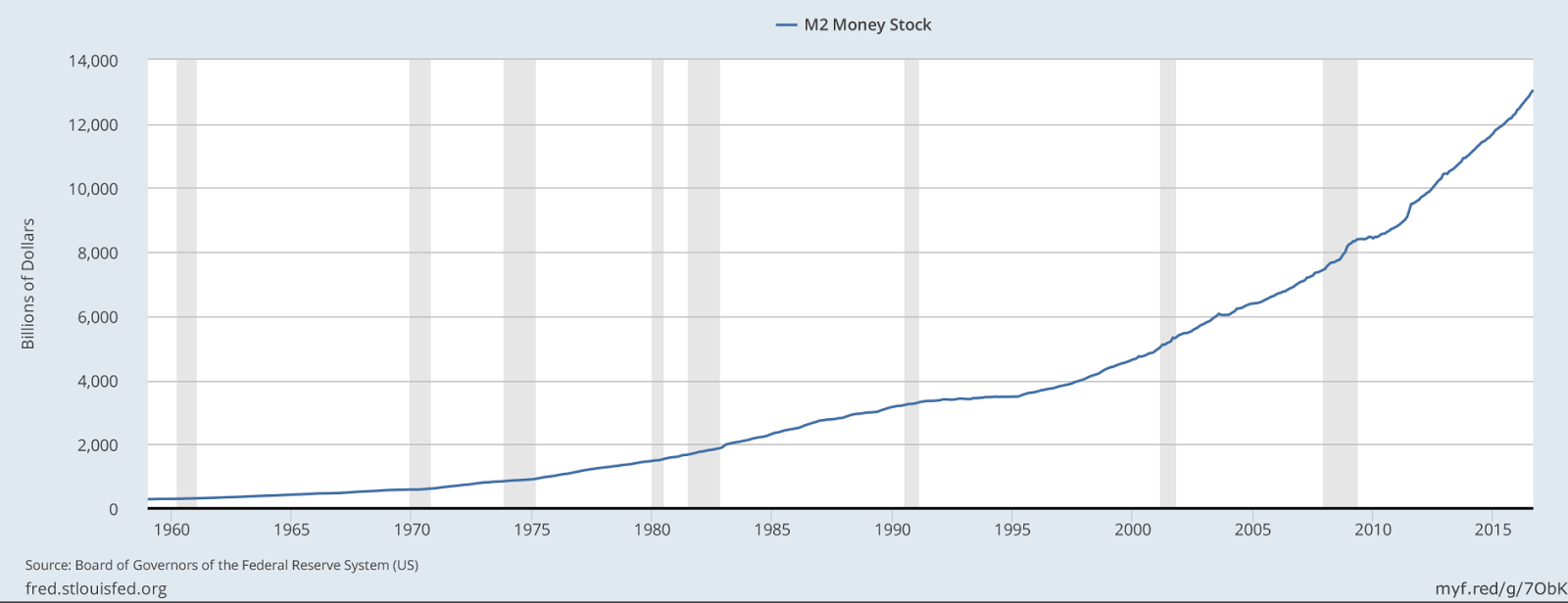
As a former full time trader on the NYSE and NASDAQ, I'm surprised an important observation on our economy has not been discussed openly in the financial news media. Most of my compatriots in the semiconductor industry are avid statisticians and share similar backgrounds in statistical process control, business planning and economic forecasting. However, I suspect many have not have seen data on the velocity of our economy (I've not seen this discussed). Here's the problem in plain sight (if you know where to look). The M2 money supply is steadily increasing as the Federal Reserve attempts to stimulate the economy.


See the FRED M2 Money Supply chart below:
(click on chart to enlarge)


Source: Federal Reserve Economic Data

As the money supply is increasing, its velocity is decreasing and headed for a crash (this phenomenon is not being discussed). What is velocity? The M2 velocity is the rate at which money changes hands. Currently, when consumers receive a pay check, most earnings stay in the bank after essential monthly bills are paid. Velocity increases with discretionary spending; the purchase of consumer goods, dining out, entertainment etc. (these activities stimulate the economy and velocity). The M2 Velocity is in an alarming dive as consumers continue to loose more of their discretionary income. The bulk of the money supply increase is being consumed by Wall Street which explains the rise in the stock market and the decline of middle class (and low income) households. As such, there is no real economic recovery in progress as reality is being masked by Wall Street prosperity.


See the FRED M2 velocity chart below:
(click on chart to enlarge)


Source: Federal Reserve Economic Data


We continue to see news stories about Wall Street gains along with monthly cheers for small, incremental increases in the employment rate while puzzling over our economic stagnation. The Obama administration recently ceased the publication of the complete scale of unemployment data publishing only the U3 component which approximates 4.9%. The current, actual U6 unemployment component which totals all unemployed and those who would like to work, approximates 9.5% (see the Bureau of Labor Statistics Table A-15 for the full data set which is still published) . With almost 10% of our nation unemployed we have a serious problem. Federal Reserve Chair Janet Yellen correctly observed and reported the unemployment dilemma immediately after taking office. Interestingly, I've not seen her discuss the M2 Velocity problem. The economy is stalled like an airplane with insufficient speed to remain airborne. As the inflation rate is in single digits, Yellen is reluctant to raise interest rates for fear of stalling the M2 velocity further and crashing our consumer economy even though Wall Street continues to benefit from the economic stimulus of the M2 money supply. Click here to see the current (complete) unemployment data chart from the US Bureau of Labor Statistics.Obama Care has crippled the economy, placing greater financial burdens on employers and individuals alike by discouraging the hire of new, full time employees and increasing health care insurance premiums and deductibles. We need to restore a competitive economic environment (on many fronts) and secure full employment for all Americans if we are to again achieve economic prosperity for our nation. For more Federal Reserve Economic Data (FRED) visit https://fred.stlouisfed.org/ 

Be sure to vote on November 8.

Corrections and clarification:

In reviewing this post I must correct/clarify/qualify my excerpted statements below:

Currently, when consumers receive a pay check, most earnings stay in the bank after essential monthly bills are paid.”

The M2 Velocity is in an alarming dive as consumers continue to loose more of their discretionary income.”

While the M2 is in an alarming dive, the fact is that currently reported FRED data indicates an incremental increase in discretionary income and consumer spending. I made the above statements based on widely reported observations and anticipation that discretionary income will likely decrease given the anticipated FY 2017 increase in costs for Obama care and related health care insurance for consumers.  While these observations may prove to be true if health care expenses increase next year as anticipated, we must use currently available data for discussion purposes. FRED defines M1 and M2 velocity data as follows:

“The velocity of money is the frequency at which one unit of currency is used to purchase domestically produced goods and services within a given time period. In other words, it is the number of times one dollar is spent to buy goods and services per unit of time. If the velocity of money is increasing, then more transactions are occurring between individuals in an economy. The frequency of currency exchange can be used to determine the velocity of a given component of the money supply, providing some insight into whether consumers and businesses are saving or spending their money. There are several components of the money supply,: M1, M2, and MZM (M3 is no longer tracked by the Federal Reserve); these components are arranged on a spectrum of narrowest to broadest. Consider M1, the narrowest component. M1 is the money supply of currency in circulation (notes and coins, traveler’s checks [non-bank issuers], demand deposits, and checkable deposits). A decreasing velocity of M1 might indicate fewer short term consumption transactions are taking place. We can think of shorter term transactions as consumption we might make on an everyday basis. The broader M2 component includes M1 in addition to saving deposits, certificates of deposit (less than $100,000), and money market deposits for individuals. Comparing the velocities of M1 and M2 provides some insight into how quickly the economy is spending and how quickly it is saving.”

Source: Federal Reserve Bank of St. Louis, Velocity of M2 Money Stock [M2V], retrieved from FRED, Federal Reserve Bank of St. Louis; https://fred.stlouisfed.org/series/M2V, November 8, 2016.

My apologies for any confusion concerning this data.

Thomas D. Jay 11/8/2016


Regards to all.

Thomas D. Jay
Semiconductor Industry Consultant

Thomas.Dale.Jay@gmail.com
https://ThomasDaleJay.blogspot.com
Thomas D. Jay YouTube Channel

Visit my new Amateur Radio blog at:
www.WA2HXR.blogspot.com


Corporate, private entities or publications referenced or linked in this article are the respective owners of their logos, trademarks, service marks, media content and intellectual property. Unless otherwise disclosed, Thomas D. Jay has no financial interest in companies referenced in blog articles or other published media communications. Thomas D. Jay is not a registered financial advisor. No representation is made to either buy or sell securities. Opinions expressed by Thomas D. Jay are his own. Thomas D. Jay does not employ or otherwise utilize/authorize third party agents to express his opinions, represent his interests or conduct business on his behalf except where formally contractually designated. Thomas D. Jay does not agree to indemnify or hold harmless vendors, clients or third parties to related contractual agreements and reserves the right to applicable legal remedies in lieu of arbitration. These terms are subject to change. Concerned parties should check this blog site for periodic updates.

Acknowledgments and Reference Links

Federal Reserve Economic Data (FRED) web site.  https://fred.stlouisfed.org/

US Bureau of Labor Statistics Table A-15 Unemployment Data http://www.bls.gov/news.release/empsit.t15.htm

Tuesday, June 21, 2016

Future EUV/FEL Strategy – The Beam Line Approaches


As many of you know, I've been following the progress of EUV lithography over the years, observing and commenting on the program's many engineering successes as well as the delays in the convergence of EUV lithography and the anticipated HVM time line (High Volume Manufacturing). In spite of improvements in laser technology and the availability of low dose photoresists, the development of high power LPP (Laser Produced Plasma) EUV source technology >100 watts remains problematic. EUV HVM insertion remains elusive and unpredictable. The source power limitations and MTBF (Mean Time Between Failure) of LPP technology have gated the program. A few years ago many in the SPIE community sought to explore the potential of a FEL source for high power EUV applications. At the time, Free Electron Laser [1] Technology was not yet a topic for dinner table discussion so in September, 2014 I published Future FEL/EUV Strategy – The Light at the End of the Beam Line. [2] On-going FEL developments at SLAC and recent related commentary from companies like GLOBALFOUNDRIES have generated new interest in FEL technology. As many new engineers and investors have joined our ranks, I thought a more comprehensive review was in order, so I've excerpted portions of my 1994 primer on FEL/EUV strategy to point out the enabling feature/benefits of a high power, high reliability light source for EUV lithography.

What are the current obstacles to high power EUV?

In ASML's current LPP source designs, a solid state "pre-pulse" laser and a second, high energy CO2 laser are fired at micron sized tin (Sn) pellets, evaporating them and releasing EUV light as a byproduct. Knowledgeable sources have informed me that the currently employed CO2 lasers are at or near the maximum of their pulse rate capabilities, effectively limiting further power output. As more CO2 laser power becomes available, there may still be practical limitations on the scaling and feed rate of Sn (tin) target material. As determined by physics, the inherent energy conversion factor for tin approximates 4%, and further incremental improvements in efficiency are obtained with diminishing returns. Assuming additional laser power becomes available for ASML, further complications can result from higher LPP source power levels as the rate of residual particulate contamination from evaporated tin increases in approximate proportion with increased laser power. Critical beam line mirror surfaces and other source components rapidly lose their efficiencies as tin contamination accumulates, reducing the available up time of the stepper (MTBF). It was originally anticipated that an optimal LPP EUV source design would provide 13.5nm light at power levels >200 watts, providing current and future lithography requirements. However, more recent demands for even higher EUV power levels have been identified. ASML and Carl Zeiss acknowledged in an invited paper at SPIE Advanced Lithography 2015, that higher resolutions will require 60mJ/cm2 for half pitch nodes <8nm. [3] ASML's recent (2015) collaboration with Carl Zeiss has produced an optical system with a numeric aperture (NA) of 0.55 vs. ASML's current EUV NA of 0.33. The higher NA system will require 500 watts of EUV power to achieve the estimated 60 mJ/cm2 dosimetry required for throughput of 150 wafers/hour. While this concept extends the viability of 13.5nm lithography, the delivery of a reliable 500 watt EUV source remains a critical item on the agenda, meaning the availability of free electron laser technology will probably gate related programs. A recent article appearing in the SPIE News Room, Extending extreme-UV lithography technology, [4] suggests that power levels of 500 – 1000 watts may be required for a single stepper necessitating a large scale central source EUV FEL.

A Primer on Free Electron Lasers

What is a free electron laser and how is it different from conventional lasers and LPP systems? To answer this question we must entertain the convergence of the US DOE's high energy physics community with the semiconductor industry and discuss recent innovations in technology. In previous and current generation stepper and scanner systems, it's been common to utilize laser light sources producing the desired wavelengths required for semiconductor photolithography. In current 193nm lithography systems, an argon fluoride (ArF) laser produces the light. The laser light produced is monochromatic, of sufficient brilliance and provides many hours of trouble free uptime. It would seem this simplistic approach might be applied to EUV lithography. Why not build an EUV laser with a wavelength of 13.5 nanometers? This has not been possible due to limitations in physics. The highly reflective optics required for laser efficiencies have yet to be created for EUV spectra. Current Bragg cell mirrors reflect EUV with a closely approximated 90% efficiency. However, FEL is a game changer. Some history and an analogy:


The term LASER is an acronym for Light Amplification by Stimulated Emission of Radiation. The first solid state, 694nm synthetic ruby laser produced at Hughes Research in 1960, [5] utilized xenon flash lamps to inject high energy photons throughout the core of a ruby rod, stimulating the emission of photons from its lattice structures. Lasers operate at specific wavelengths which are determined by the seed (or lazing) material's inherent spectral signature. The 694nm wavelength is derived from the band gap emissions of the ruby's crystalline composition. We might compare the ruby crystal in this laser with a quartz crystal in a radio which determines its operational frequency. Accordingly, we might otherwise assign “channel I” as an identifier of I-line photolithography operating at 365nm.

The Foundation Physics of FEL
 A Radio Logical Analogy

A radio transmitter's frequency has historically been controlled by quartz crystal elements. Y-cut quartz crystals oscillate (vibrate) at specific frequencies which are dependent upon their thickness. The thinner the crystal, the higher the frequency obtained. Inversely, the thicker the crystal, the lower the frequency obtained. Passing an electric current through a quartz crystal induces it to oscillate at its inherent resonant frequency, so determined by its thickness. The frequency produced is extremely stable and the resulting wave form is of high purity, providing an excellent medium for control of radio frequencies and instrumentation. Crystals also produce harmonic frequencies. A harmonic is a multiple of the crystal's fundamental resonant frequency. As such, a crystal oscillating at 3 MHz will also produce a weaker signal at 6MHz (its second harmonic frequency), and a still weaker third harmonic at 9MHz and so on. When impractical to manufacture crystals at their desired fundamental frequencies, "third overtone" crystals are often utilized to provide a harmonic frequency which can be sufficiently amplified and utilized as an effective fundamental frequency, thus extending the upper limits (and our usage) of the radio spectrum. Even with clever engineering, over the years radio frequency control became problematic as multi-channel communication systems evolved, requiring large banks of crystals to span a given range of frequencies; one crystal required for each channel frequency. Rather than utilize thousands of crystals to span the radio spectrum, communications equipment evolved to employ a frequency control device called a VFO: a Variable Frequency Oscillator. In this scenario, several fundamental frequency crystals and specially designed varactor diode/phased locked loop circuits comprise a heterodyne oscillator, sometimes known as an IF (Intermediate Frequency) mixer. Such an oscillator can generate a wide range of possible frequency combinations by mixing (heterodyning) the output obtained from the crystals to produce the desired sum/difference of their frequencies by way of constructive or destructive interference. As a VFO radio tuning dial is manipulated, it changes one of the mixing frequencies to produce the desired sum/difference operational frequency for both transmitter and receiver. The advantage to such a design is the elimination of separate transmitter/receiver controls, and thousands of individual crystals normally assigned for each desired radio channel. The conceptual use of both harmonic and sum/difference frequency synthesis has found its way into many applications in physics and electronics.

Free Electron Laser Fundamentals

Imagine that we might adjust and control a laser's wavelength using a concept similar to a radio's Variable Frequency Oscillator but with a different set of physics. By electronically tuning a laser's wavelength, we can eliminate the need for specialized crystalline, gaseous or other lazing materials and operate outside the spectral wavelength segments they are physically limited to. FEL technology can produce tunable wavelengths of light throughout the microwave, visible spectrum and x-ray regime. A free electron laser is comprised of a large beamline/electron source which accelerates electrons to near the speed of light. On opposite sides of the electron beam line are interposed field coils of opposing polarity called undulators or "wigglers", which when energized establish a transverse sinusoidal field across the beam path. Electrons accelerated into the transverse field produce incoherent photons in a mixed assortment of sinusoidal wavelengths sometimes referred to as “bunches”, emitting photons at wavelengths determined by their acceleration and the transverse field strength (synchrotron radiation). By adjusting the electron beam energy or the magnetic field strength of the undulators, the wavelength of the emitted photons can be tuned selectively to produce coherent light. Variations on this concept have evolved as follows:

A Tunable SASE FEL

A SASE FEL is able to produce laser light over a broad range of spectrum without the requirement for conventional lazing materials such as ruby crystal or argon fluoride etc. In a tunable SASE (Self Amplified Spontaneous Emission) FEL, high energy source electrons passing through an undulator can produce an assortment of incoherent photons (initially at randomly different wavelengths) which become bunched in the transverse sine wave and interact via constructive or destructive interference, producing incidental derivative wavelengths (spontaneous emission). That is to say the bunched photons add and subtract their wavelength values from one another producing new sum/difference valued photons at the mathematically resulting wavelengths. When tuned to a specific wavelength of interest by adjusting the electron beam energy or the magnetic field strength of the undulators, such subsequently produced photons arrive in phase (at the same wavelength) and cumulatively intensify to release high energy coherent laser light (self amplification). While a very useful concept for a variety of applications, the spontaneous emission in a SASE FEL can propagate statistical artifacts resulting from the inherent mathematical sum/difference phenomenon, and consequently can produce a beam exhibiting limited shot to shot reproducibility. As such, the utility of a SASE FEL might be limited in applications which require extremely accurate dosimetry. The limited shot to shot reproducibility might also contribute to the dosimetry phenomenon known as “shot noise”.

A Tunable HGHG FEL

FEL performance can be modified and improved by utilizing an external seed laser as a source wavelength. The seed laser is a conventional laser utilizing a material such as ruby crystal (one example) to produce a monochromatic feed source of photons. In an HGHG (High Gain Harmonic Generation) FEL, the seed laser interacts with the electron beam as it propagates through the first undulator (called a modulator), tuned to the seed laser's wavelength. The resulting interaction with the seed laser induces coherent modulation of the electron beam energy, creating photon bunching as well as consequential harmonic propagation (photons which are the mathematical multiples of the seed laser's wavelength). The micro-bunched beam of photons are then injected into a long undulator tuned to the desired harmonic wavelength. The desired wavelength comprised of harmonically produced photons arrive in phase and cumulatively intensify to release high energy coherent light at the newer, shorter wavelength of interest. A recent FERMI paper illustrates 500 shot reproducibility of 8th harmonic spectra at 32.5nm (obtained from a 260nm seed laser) exhibiting normalized photon/energy stability in the order of 7x10^-5 (root mean square), a marked improvement over previous SASE FEL data obtained over the same photon energy range. The high purity monochromatic spectra of an HGHG seed laser improves the system's shot to shot repeatability as its mode of operation does not incur the statistical deviation phenomena found in spontaneous emission spectra typically observed in a SASE FEL. As such, an HGHG FEL might be more advantageous for use in EUV applications requiring highly precise dosimetry, possibly reducing shot noise phenomenon. 

The EUV Source Challenge Ahead

Large scale projects are underway to build FEL systems to accommodate a wide range of wavelengths and scientific applications. FEL is next generation laser technology which is perhaps the best candidate to replace the LPP/EUV source designs currently offered by ASML.

Known for its work in actinic inspection at the 13.5 nm EUV wavelength, Lawrence Berkeley CXRO Lab [6] is also part of a DOE consortium currently working on LCLS-II (Linac Coherent Light Source-II) [7] at Lawrence Livermore and SLAC. Last June at the 2015 International Workshop on EUV Lithography in Maui, Aaron Tremaine of SLAC presented a comprehensive review of possible FEL designs that might be considered for EUV lithography and identified the consortium of DOE laboratories participating in the EUV FEL program. The Who's Who list of DOE participants includes SLAC, Lawrence Berkeley National Labs, Fermilab, Argonne National Lab, Cornell, UCLA, RadiaBeam, AES and Radiasoft. In order to appreciate the scale and capital intensity of this project it becomes necessary to review Aaron Tremaine's 2015 EUV Litho, Inc. Workshop presentation, LCLS-II and Free electron laser drivers for EUV Lithography [8]. The report describes FEL design considerations and recommends a “Straight Shooter” beamline configuration for semiconductor EUV lithography applications. The report addresses Erik R. Hosler's (GLOBALFOUNDRIES) 2015 SPIE publication, “Considerations for a free-electron laser based extreme-ultraviolet lithography program”, (Proc. of SPIE Vol. 9422, 94220D, 2015). The good news is that many new FEL programs are in progress [9] and the LCLS-II at SLAC might provide a viable, solution for HVM/EUV lithography. More recently, visible collaboration between GLOBALFOUNDRIES and SLAC has established the ground work for possible in-fab FEL source designs. The subsequent challenge for any future FEL/EUV initiative, is that once again the convergence of the semiconductor industry and our national laboratory community will be required to deliver future lithography source technology for EUV and beyond.

ASML has taken the lead in providing viable interim EUV technology permitting the characterization of materials, resists, masks and process precision required for future generation lithography. Double patterning techniques utilizing 193i lithography will continue to enable CDs =<10nm. We can also speculate how 13.5nm multiple patterning might enable future nodes and continued process development. In the interim, the current ASML LPP/EUV initiative has enabled the ground work our industry requires for future precision nanometer scale lithography.

Let's continue working together to secure next generation EUV and the preservation of Moore's Law.

During the course of researching this article I digested many components of the SLAC Conceptual Design Report for the LCLS-II (Linear Coherent Light Source).  Among many, two components of the LCLS-II are the SXR (Soft X-Ray) and HXR (Hard X-Ray) undulators and their respective beam lines.  It is with some amusement that my FCC designated amateur radio call sign is WA2HXR which I acquired in 1970. It should be noted that my amateur radio operations are restricted to applicable licensed amateur radio frequency spectra which excludes X-Ray wavelengths.  
CQ SLAC CQ SLAC CQ SLAC DE WA2HXR K.     73   

Click here to download this article.

Thomas D. Jay
Semiconductor Industry Consultant
Thomas.Dale.Jay@gmail.com
https://ThomasDaleJay.blogspot.com
Thomas D. Jay YouTube Channel

Visit my new Amateur Radio blog at:
www.WA2HXR.blogspot.com


Corporate, private entities or publications referenced or linked in this article are the respective owners of their logos, trademarks, service marks, media content and intellectual property. Unless otherwise disclosed, Thomas D. Jay has no financial interest in companies referenced in blog articles or other published media communications. Thomas D. Jay is not a registered financial advisor. No representation is made to either buy or sell securities. Opinions expressed by Thomas D. Jay are his own. Thomas D. Jay does not employ or otherwise utilize/authorize third party agents to express his opinions, represent his interests or conduct business on his behalf except where formally contractually designated. Thomas D. Jay does not agree to indemnify or hold harmless vendors, clients or third parties to related contractual agreements and reserves the right to applicable legal remedies in lieu of arbitration. These terms are subject to change. Concerned parties should check this blog site for periodic updates.

Acknowledgments and Reference Links

[1] Free Electron Laser
Wikipedia

[2] Future FEL/EUV Strategy – The Light at the End of the Beam Line
Thomas D. Jay, Blog Publication, September 20, 2014

[3] ASML and Carl Zeiss acknowledged in an invited paper at SPIE Advanced Lithography 2015, that higher resolutions will require 60mJ/cm2 for half pitch nodes <8nm
SPIE Proceedings

[4] Extending extreme-UV lithography technology
SPIE News Room, Erik R. Hosler, Obert R. Wood II, Moshe E Preil

[5] The first solid state, 694nm synthetic ruby laser produced at Hughes Research in 1960
Wikipedia

[6] Lawrence Berkeley CXRO Lab
Lawrence Berkeley National Labs CXRO Web Site

[7] Linac Coherent Light Source-II
Stanford Linear Accelerator Web Site

[8] LCLS-II and Free electron laser drivers for EUV Lithography
Aaron Tremaine Presentation, SLAC
EUV Litho, Inc. Web Site, 2015 Program, Maui

[9] many new FEL programs are in progress
University of California, Santa Barbara FEL Web Site
Site Maintained by G. Ramian